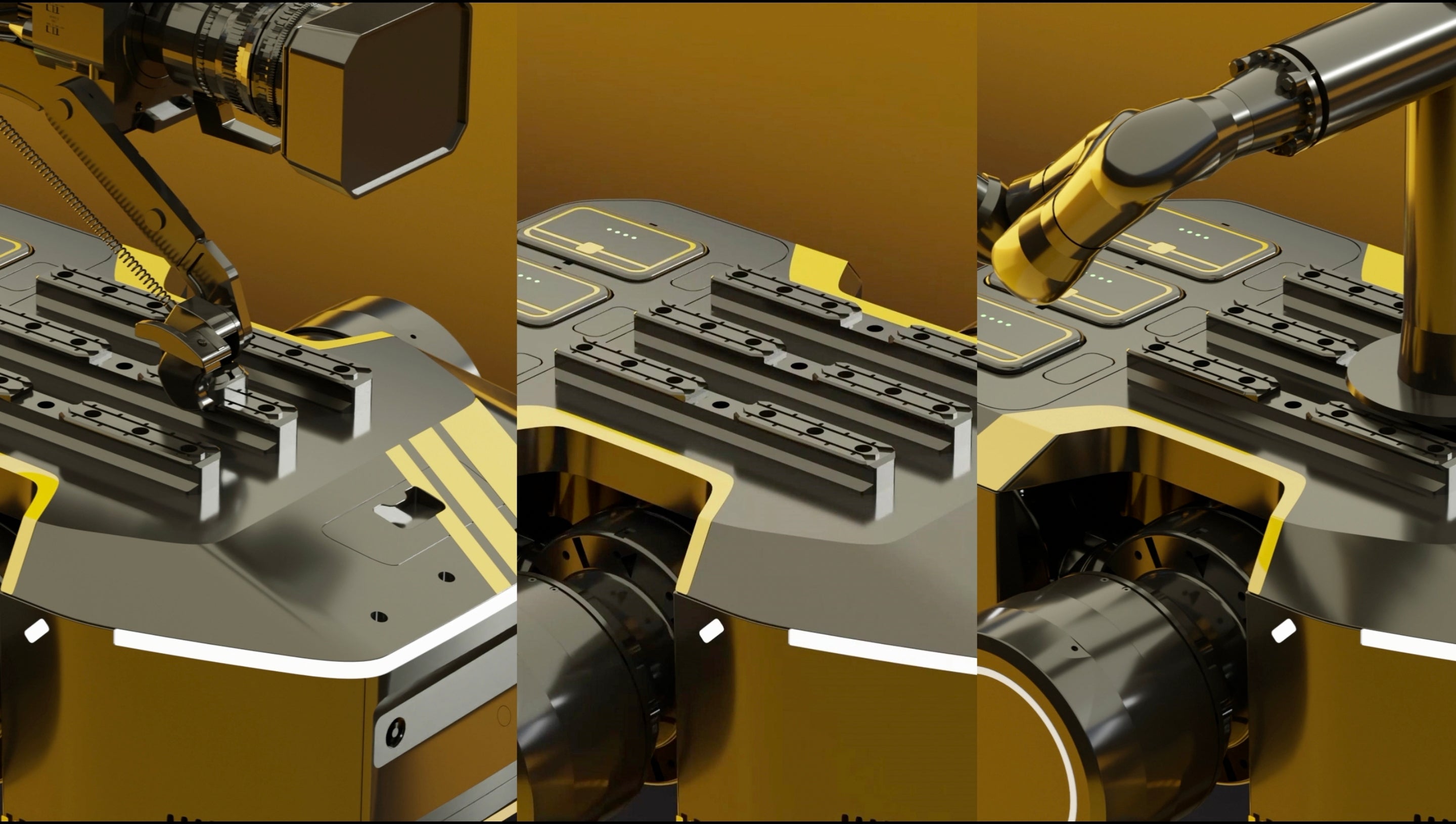
A 3D mapping project with a wheeled bipedal robot requires clear goals, suitable sensors, and accurate data processing. A practical workflow includes selecting a robot platform, configuring LiDAR and cameras, planning autonomous routes, and validating point-cloud accuracy. Modern robotic mapping systems can achieve centimeter-level accuracy, reduce manual surveying time by 30%–50%, and generate digital models for factories, warehouses, construction sites, and infrastructure inspection.
A wheeled bipedal robot mapping project starts with defining the area, expected accuracy, and final data format. A factory inspection task may require equipment-level models with 5–10 mm accuracy, while a warehouse inventory map may only need 3–5 cm precision. The project plan should specify whether the output will be a point cloud, 3D mesh, BIM model, or navigation map.
A mapping mission without a clear output target often creates unnecessary data collection. A 2022 survey of mobile mapping applications showed that most industrial projects combine LiDAR data with visual information because geometry alone cannot provide equipment labels, surface details, or object recognition.
The robot platform selection affects how efficiently data can be collected. Wheeled bipedal robots combine low-energy wheel movement with leg-based adjustment ability. Wheels allow fast travel on smooth floors, while articulated legs help the robot pass small steps, uneven surfaces, and narrow passages. Compared with traditional wheeled platforms, this design can improve movement flexibility in mixed environments.
The mechanical structure must support sensor stability because mapping accuracy depends on consistent sensor positioning. A LiDAR unit mounted on a vibrating platform can introduce point-cloud distortion during acceleration or turning. For many industrial applications, the sensor mounting error should remain below a few millimeters to maintain reliable reconstruction results.
A typical mobile mapping platform integrates several sensors operating at different frequencies. LiDAR systems commonly run at 10–20 Hz, cameras at 20–60 frames per second, and IMUs above 100 Hz, requiring accurate timestamp synchronization during data collection.
Sensor selection should match the environment and mapping purpose. Indoor facilities usually rely on LiDAR SLAM because GPS signals are unavailable, while outdoor projects may combine LiDAR, GNSS, and visual sensors. A common sensor configuration includes:
| Sensor | Main function | Typical specification |
|---|---|---|
| 3D LiDAR | Point-cloud collection | 50–300 m range |
| RGB camera | Texture and object information | 12–48 MP |
| Depth camera | Short-range perception | 1–10 m range |
| IMU | Motion measurement | 100–1000 Hz |
| GNSS | Outdoor positioning | centimeter-level RTK accuracy |
The data quality depends on how these sensors work together. A LiDAR scanner records the shape of the environment, while cameras provide color and object information. The IMU helps estimate robot movement between scans. When sensor data is properly synchronized, SLAM algorithms can build a continuous map with reduced positioning errors.
A wheeled bipedal robot such as the TITA 8DOF robot can be integrated with mapping sensors and autonomous navigation systems for complex environments. Robots with multiple degrees of freedom provide additional body adjustment capability, allowing sensors to maintain a stable scanning position when moving across different surfaces.
In robotic mapping projects, sensor placement is often tested before full deployment. A change of only 10–20 cm in LiDAR height can influence the captured viewpoint, especially in environments containing shelves, pipelines, or machinery.
Before starting data collection, the project team should analyze the environment. Factors such as lighting conditions, reflective materials, moving objects, and floor conditions influence mapping performance. Large indoor spaces with repeated structures can make localization more difficult because the robot receives fewer unique visual or geometric features.
A pre-mapping inspection normally includes:
| Inspection item | Purpose |
|---|---|
| Floor condition | Check wheel and leg movement |
| Communication coverage | Maintain robot connection |
| Restricted areas | Define safe routes |
| Object density | Estimate navigation difficulty |
| Lighting condition | Evaluate camera performance |
Route planning determines how efficiently the robot covers the area. Autonomous exploration methods allow robots to select unknown areas and continue mapping without manual control. Coverage planning algorithms are commonly used in warehouses, offices, and industrial buildings.
A 2021 study on autonomous mobile robots reported that optimized path planning reduced unnecessary travel distance by approximately 25%–40% compared with simple manual routes in large indoor environments.
The navigation system usually contains several software layers. The perception layer receives sensor information, the localization layer calculates robot position, the planning layer generates routes, and the control layer manages wheel and leg movement.
| Software layer | Main task |
|---|---|
| Perception | Process LiDAR and camera data |
| Localization | Estimate robot position |
| Mapping | Build environmental model |
| Planning | Select movement path |
| Control | Execute motion commands |
Battery planning should be included before field operation. Mapping requires continuous power for motors, sensors, and onboard computers. A robot equipped with LiDAR, cameras, and computing units may consume several hundred watts during active scanning. Battery capacity should be calculated according to mission distance, scanning time, and charging availability.
For large facilities, mapping tasks are usually divided into several sessions. A robot may complete one zone, return for charging, and continue from the previous position. This approach helps maintain consistent data quality across large areas.
A practical industrial mapping mission lasting 4–8 hours often requires multiple battery cycles, especially when the robot performs autonomous navigation and high-resolution scanning at the same time.
After collection, raw sensor data needs processing before becoming a usable 3D model. Point clouds normally contain noise caused by moving objects, sensor vibration, and reflective surfaces. Processing software removes unnecessary points, aligns different scanning sessions, and improves the final model.
The common processing workflow includes:
| Processing stage | Result |
|---|---|
| Data filtering | Remove noise points |
| Registration | Combine multiple scans |
| Optimization | Improve alignment accuracy |
| Reconstruction | Generate 3D model |
| Export | Create engineering files |
The final model format depends on the application. Facility managers may need a detailed point cloud for equipment inspection, while architects and engineers may require BIM-compatible models. Mining, energy, and transportation projects often use georeferenced 3D models for long-term monitoring.
Accuracy verification should be completed before using the final data. Reference points, measured distances, and independent surveying methods can be compared with the generated model. For many industrial projects, errors below 2–5 cm are acceptable, while precision manufacturing environments may require millimeter-level accuracy.
A 2023 review of robotic mapping technologies reported that modern LiDAR-based systems can achieve centimeter-level accuracy when calibration, localization, and environmental conditions are properly controlled.
Project maintenance should also be considered after deployment. Mapping robots require regular sensor calibration, software updates, battery checks, and mechanical inspection. Changes in the environment, such as new equipment placement or building modifications, may require additional scanning sessions.
A complete 3D mapping project with a wheeled bipedal robot combines robot hardware, sensor technology, autonomous navigation, and data processing. Careful planning of mission requirements, sensor setup, route design, and quality checking allows organizations to create accurate digital representations of real environments for inspection, management, and future automation.